Send and Receive CAN Frames in INCA
This guide walks through receiving and transmitting CAN frames in ETAS INCA with a CANmeleon device running ETAS ES582 firmware (ES582.1).
Screenshots below show INCA V7.2.10 with its Chinese UI; English menu equivalents are provided alongside the Chinese labels.
Prerequisites
- Completed ES582 Windows Driver Setup, including the ES582 USB driver, HSP, and BOA EBI Distribution Package.
- Both Windows Device Manager and the HSP Update Tool (
HSP-UT) recognizeES582.1. CAN_H,CAN_L, andCAN_GNDare properly wired to the target bus with 120 Ω termination at both ends.- You know the target bus channel, bitrate, CAN IDs, frame format (Standard or Extended), and transmit cycle times.
Create a Database and Workspace
Launch INCA and create a new database or open an existing one.
Add a Workspace (
工作区) in the database tree.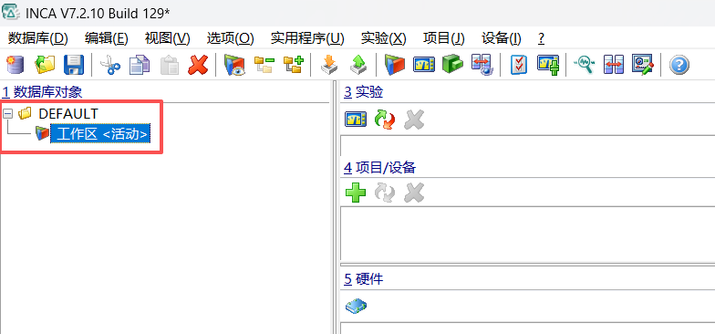
Open the Hardware Configuration (
硬件) window for the workspace.Click Search for Hardware (
搜索已连接的设备, magnifying-glass icon) on the toolbar and verify thatES582.1appears with its serial number.Expand the target CAN channel under
ES582.1, select CAN-Monitoring or CAN-Output according to your test task, and click OK to add it to the hardware configuration.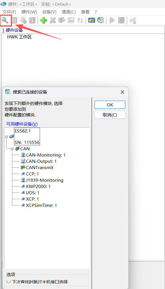
Receive CAN Frames
1. Configure CAN-Monitoring
- Select CAN-Monitoring in the Hardware Configuration tree.
- On the Parameters (
参数) tab, set the CAN channel, bitrate, and frame format to match the physical bus. - Save the configuration and click Initialize Hardware (
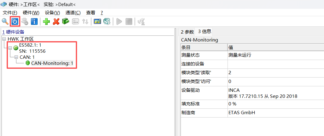
初始化硬件). - Confirm that
ES582.1, theCANchannel, andCAN-Monitoringall display active green status indicators.
2. Create an Experiment and Select Variables
Return to the INCA Database Manager and create a new Experiment (
实验) linked to the workspace.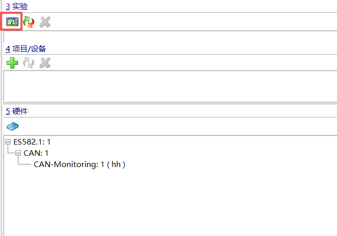
Open Variable Selection (
变量选择) in the Experiment Environment.Under the CAN-Monitoring data source, select the message byte variables you want to inspect.
Byte0–Byte7work well for a quick check; for extended measurements, select only the signals or bytes required by your test to minimize unnecessary display updates.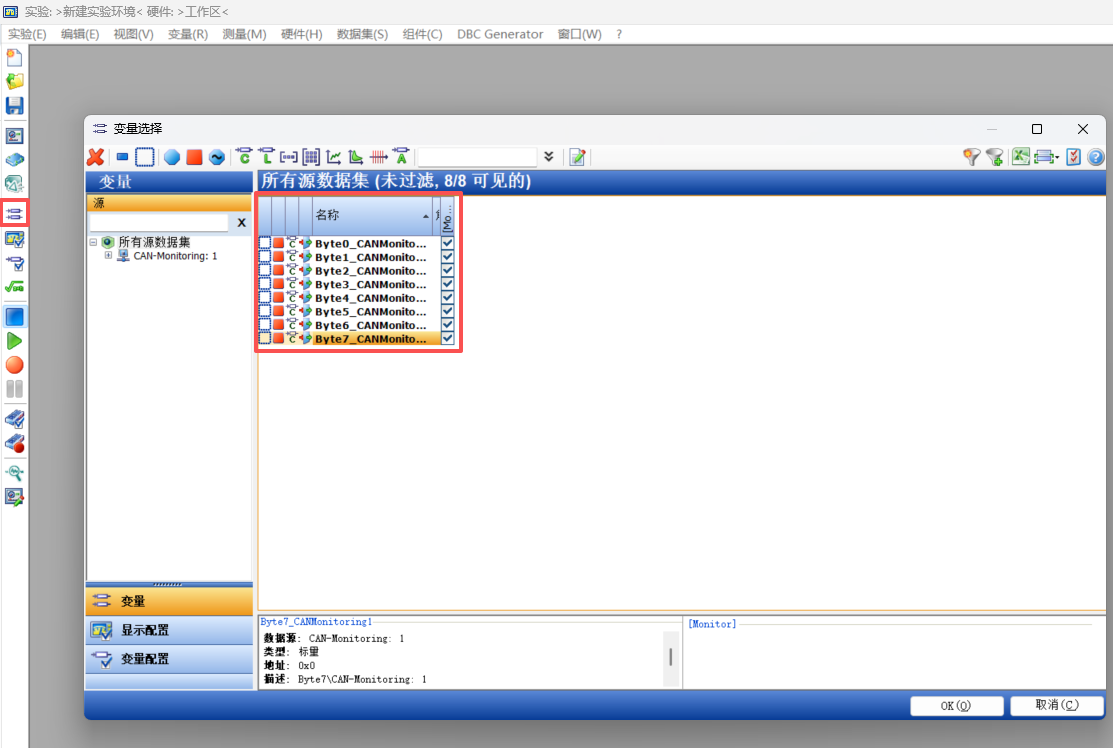
3. Start Measurement
- Add the selected variables to a measurement display window.
- Click Start Measurement (
开始测量). - Verify that incoming byte values update continuously and cross-check them against known bus traffic or a second bus analyzer.
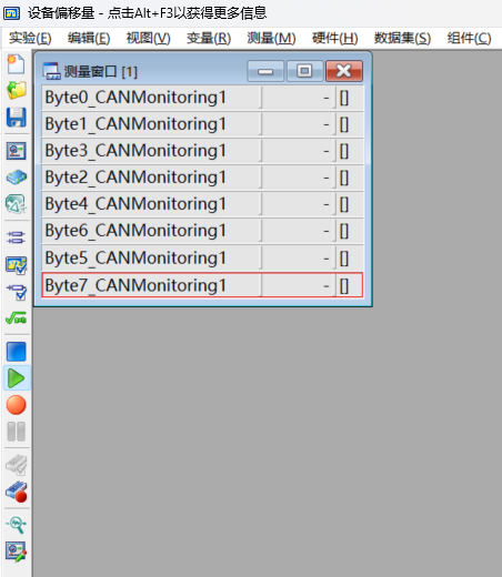
If values remain blank, stop the measurement first and check the physical channel, bitrate, termination, and whether another node is actively transmitting on the bus—avoid repeatedly re-initializing hardware with unverified bus parameters.
Transmit CAN Frames
1. Add CAN-Output
Add CAN-Output under the target ES582.1 CAN channel in the Hardware Configuration. CAN-Monitoring and CAN-Output can coexist in the same configuration as long as both reference the intended channel and matching bit timing.
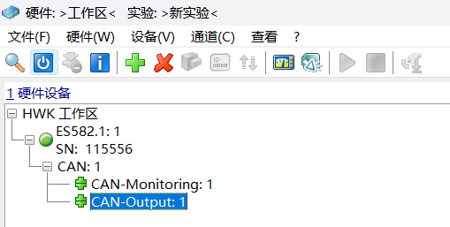
2. Create a CAN Message List
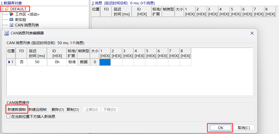
- Return to the INCA Database Manager and create a CAN Message List (
CAN 消息列表). - In the CAN Message List Editor (
CAN消息列表编辑器), click New Data Frame (新建数据帧) and configure the CAN ID, Standard/Extended identifier, DLC, payload bytes, and delay/cycle time (ms) for each frame. - Review every field against your project's approved message specification, then click OK to save.
3. Bind the Message List to CAN-Output
- Reopen the Hardware Configuration and select CAN-Output.
- Open the Main Lists (
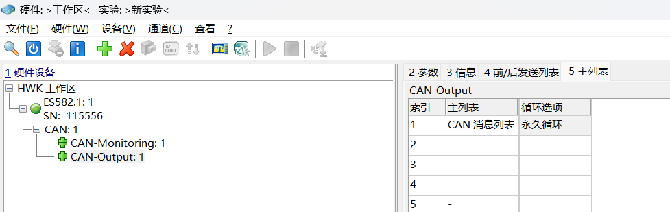
5 主列表) tab and assign your newly created CAN Message List. - Choose single-shot or cyclic transmission (
循环选项) according to your test; double-check the configured cycle time before enabling cyclic output. - Initialize hardware, open the experiment, confirm normal bus status, and start transmission.